
Nearly there, I can almost taste it!
Yeah, it tastes like furniture 🙂 .
Last week we had just finished installing breadboard ends on both top panels. Now we’ll look to mounting and hinging the panels. Before going further however, I’d like to position and mount the lower panel to the carcass.
As discussed in the last chapter, the bottom panel will be secured in the center of its width and allow movement outward towards the front and back of the cabinet during the seasonal humidity changes.

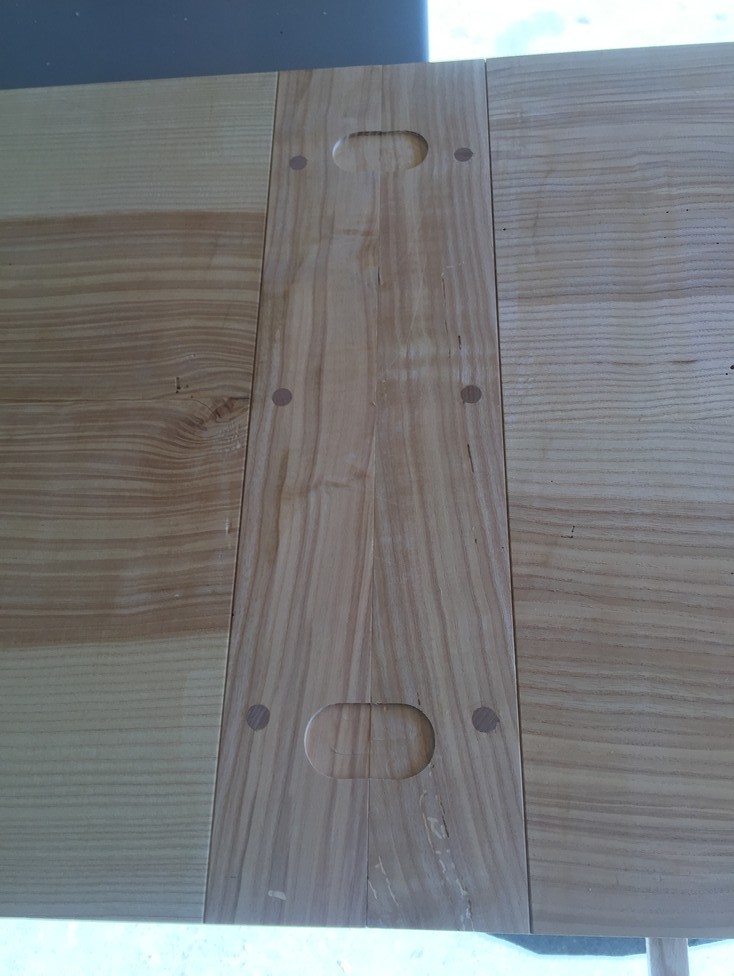
The screws that fasten the front and back of the panel will have elongated screw holes in order to accommodate the wood movement. Before worrying about that, I decide where the holes will be and drill them normally. Each pedestal will get six screws. There will also be two that are positioned in the very center (as looking at the front of the cabinet), front and back.

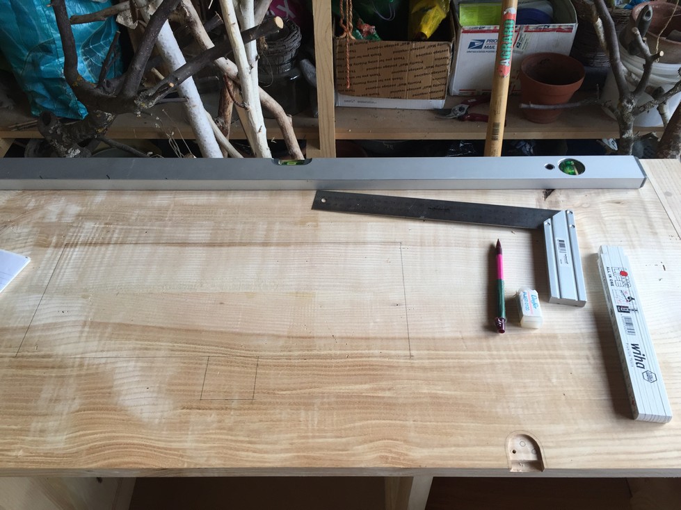
Because I don’t trust the flatness of my garage floor, I put the carcass up on the machine table and shim it till its level. Then I ensure that the panel is positioned evenly left to right. There is to be a 10mm overhang at the front when the doors are closed so that is also measured prior to clamping the panel in place.


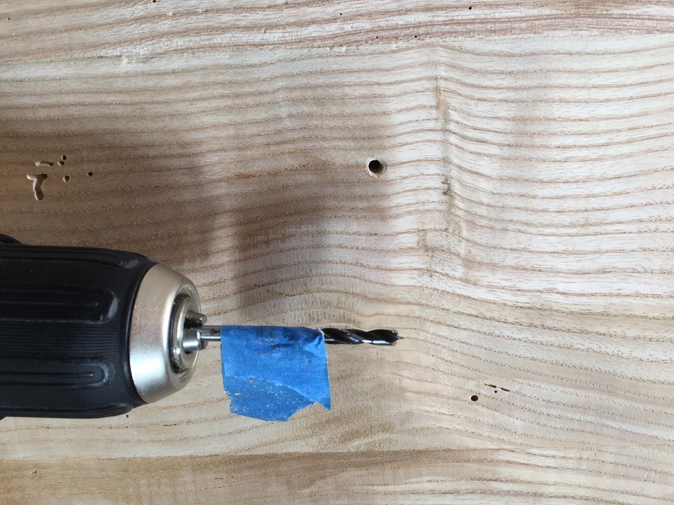
With the panel clamped, I can use a brad point bit to mark the center of each screw hole on the underside of the panel. With that accomplished, I can drill pilot holes for the screws. Instead of buying yet another doo-hickie that will be more trouble than its worth, I just use some painter’s blue tape to mark the depth I want to drill. The panel is 23mm thick so I wrap the tape at 18mm.

For all but the center screw holes, I elongate the holes and then on the underside of the cross-members, carve a bevel for the screw-head.

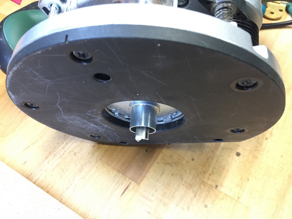
Previously, while waiting for the glue to dry on the panels, I built this hinge jig. It’s basically a way to uniformly locate the hinges on two different panels. The two small wooden fences rotate and the round cutout guides the template insert in the router. I set the depth of a straight router bit to the thickness of the hinge and route the shallow mortise (not in one step, I creep up on it to avoid cutting too deep). The two fences accurately position the hinge. Rotate the fences 180 degrees, flip the jig end for end, and route for the mating hinge mortise on the panel leaf.

Since the original plans offered the jig design based on English measurements, and I have mostly metric bits, it took me a few tries to get the jig just right and I still had to make some tweeks with a little drum sander chucked into my drill press. A few trial cuts and I thought I was good to go (I wasn’t).

I route the mortises in both panels, lay them end to end to double-check alignment and install the hinges.

By the way, since these hinges come with brass screws, it is definitely a good idea to drill the proper sized pilot hole. If the manufacturer doesn’t recommend a hole size, I use my calipers to measure the shank and start there testing on a scrap piece. Brass screws will break easily if you try to muscle them into hardwood. Also, it’s a great idea to “pre-cut” threads in the pilot hole using a steel screw before inserting the brass one.
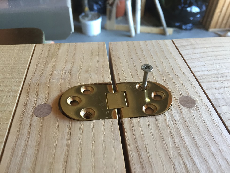
And here is the result. Everything works great but there is this huge, ugly gap for odds and ends to fall through.
I should have anticipated this but relied on the jig plan. Plans are great, they give you a good starting point and help guide the process but you still need to think about each step and modify to your specific hardware or design.
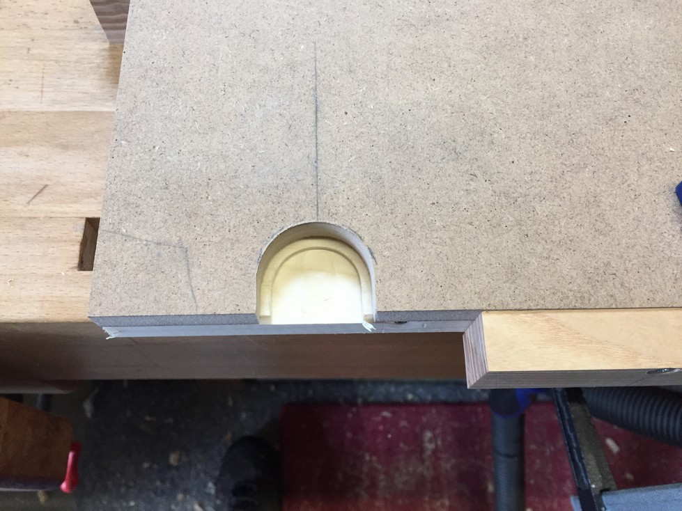
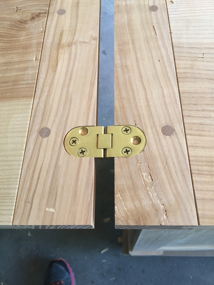
Back to the drawing board, or more accurately, the jig. I measure the gap, divide by 2, give myself a 1mm buffer, and re-work the jig so the mortise is cut further in. And that’s not all; due to the dual pivot design of the hinge, I now have to chisel out a space for the “knuckle” of the hinge to fit in the end of the panel.

And now, the new result:
A bit of extra work, but the end result is so much nicer. Also, I expect that I may be building another sewing cabinet in the future, so it’s better to get the jig set up right this time around.
Now comes a task that just tugs at my heart strings. The upper panel will be two leaves, one that folds to the left and one that folds out, so I must measure not once, not twice, but about 5 or 6 times before I’m ready; and then cut the damn thing in two pieces. I can’t tell you how much that hurt me to do…..

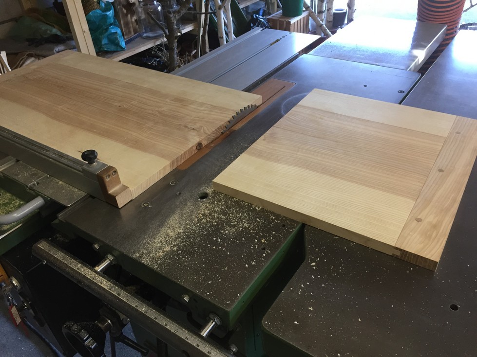
Here’s something you may want to think about if you’re ever in a similar situation: My saw blade is 3mm thick so if I had made the top panel exactly the same length as the bottom panel, I would have a 3mm gap when the leaves are closed. I wanted there to be almost no gap so I purposely made the right breadboard end a few millimeters wider than necessary so when the cut is made, the ends are flush and there is very little gap between the closed leaves.
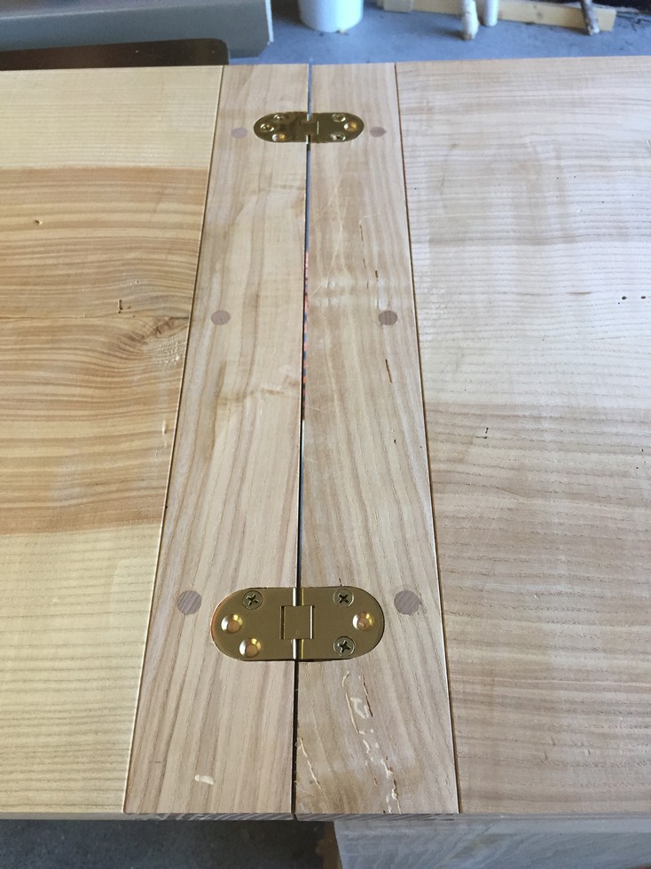
I route the hinge mortises for the smaller leaf in the same way as the large one and put it all together for a trial run.


Now for some fun with hardware: the lift. I get Monika involved again because I need to know the exact location that will be optimal. We start at the kitchen table and she puts the machine in her normal sewing position so I can make the critical measurements. These are:
- The distance from the front edge of the table to the front edge of the machine
- The minimum distance from the front of the machine to the rear (Afterwards, I will add 15-20mm to this)
- The minimum distance from the right side of the machine to the left (I’ll add about 30mm to this)

Be careful, a machine like this is not typically “square”. That’s why I use my square and not just a measuring tape to ensure accuracy.
Some additional things to think about:
- The position of the power cord and the foot pedal cord and if they need extra space (the power cord sticks out a little on the right side so adding 30mm to the minimum measurement takes care of that).
- There is a large platform that clips onto the machine for use in the secondary lift position (when the machine is lowered a bit so this platform is flush to the tabletop). This platform has a molded piece that sticks out below and so I need to cut a notch in the table to accommodate for it.
I transfer these measurements to the lower panel so I can cut out the space for the machine to raise and lower. Way back in Chapter 2 of the sewing center, I mentioned a severe design flaw. It was that the sewing machine is assumed to be in a position that is centered in the space between pedestals. Anyone that has sewing as a hobby or profession will tell you that your body is not centered on the machine itself but on the left side of the machine where the needle is located. If I had blithely followed the original design, Monika’s legs would be cramped up against the left pedestal. So we not only increased the size of the leg space but I also use the right pedestal as the reference for locating the machine as far right as possible. Now, the needle location is closer to the center of the leg space and Monika can sit comfortably while sewing (and ergonomically).
Now we get to a tricky bit. I would like to save the cut-out piece to use as the platform for the machine; that way the wood isn’t wasted. Normally, I would drill a 5mm hole at 3 corners to allow me to insert the blade of the jigsaw. If I do that, at best, the platform will have about an 8mm gap all the way around. Not only would it not look good, but it offers chances for little bits (like needles) to fall through.
There is a jigsaw trick that takes a little practice so I recommend trying this first on a few pieces of scrap. You get the jigsaw oriented so the blade is in line with the cut mark and tilt the saw forward enough so you can turn the saw on without the blade hitting the wood. You then, very slowly and carefully, rotate the saw down until the blade starts to cut. Applying just enough pressure to cut, but not so much that the blade knocks the saw out of line, you continue to rotate down until the blade breaks through the other side. This is called a “plunge cut” and can be also performed with a circular saw. If you google “jigsaw plunge cut” there are a number of good articles and videos demonstrating this technique, which is a very useful one to have in your repertoire. One valuable hint to doing this succesfully is to ensure you have a good sharp blade installed. I used a brand new blade (Bosch T101D) to make two trial cuts in scraps and then put another brand new blade in for the actual cut. $3 well spent and both blades still have a lot of life left in them.

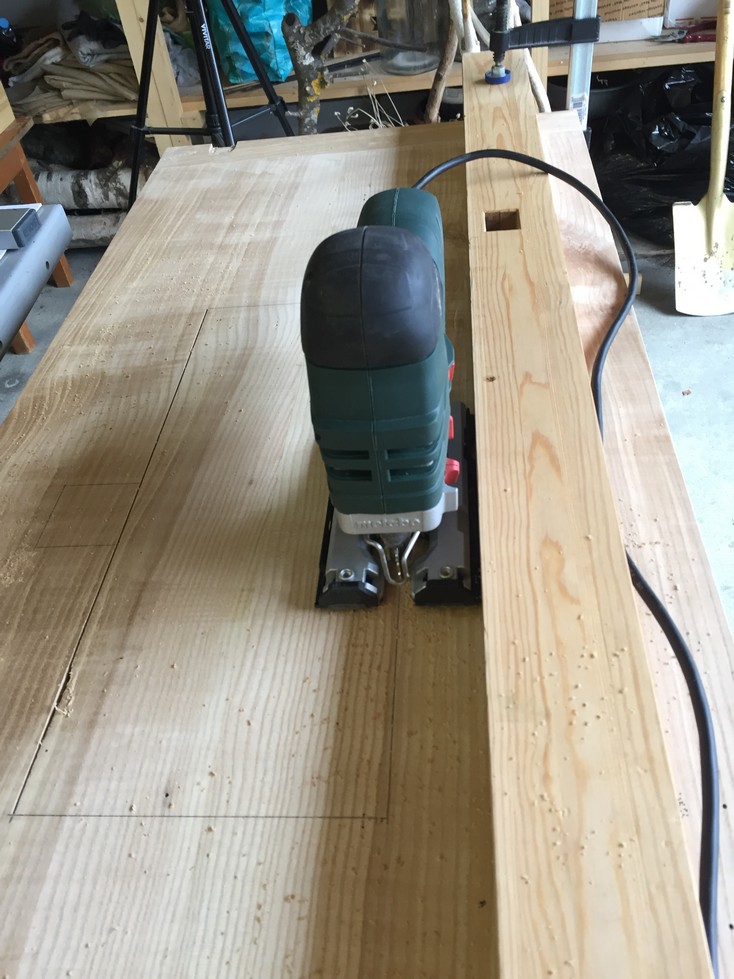
I should have taken a close-up, but you can just see the first cut at the left (on the picture above right), on the line with minimal tearout. I use a long straight piece of wood clamped to the panel as a cutting guide and am able to get nice straight cuts all the way around. For the last cut, I don’t want the piece to fall through causing damage to the cut and I can’t hold it from underneath and cut straight at the same time (I can walk and chew gum though….) so I use a couple pieces of blue painter’s tape to hold it while cutting.

No matter how careful I am, the cut is still a bit ragged so I will use the router to clean it up. I have some plywood scraps that I clamp along the line and a pattern router bit with a bearing at the top chucked into the router. The plywood acts as a pattern fence that the bearing will ride along and the bit cuts the wood flush to the pattern.
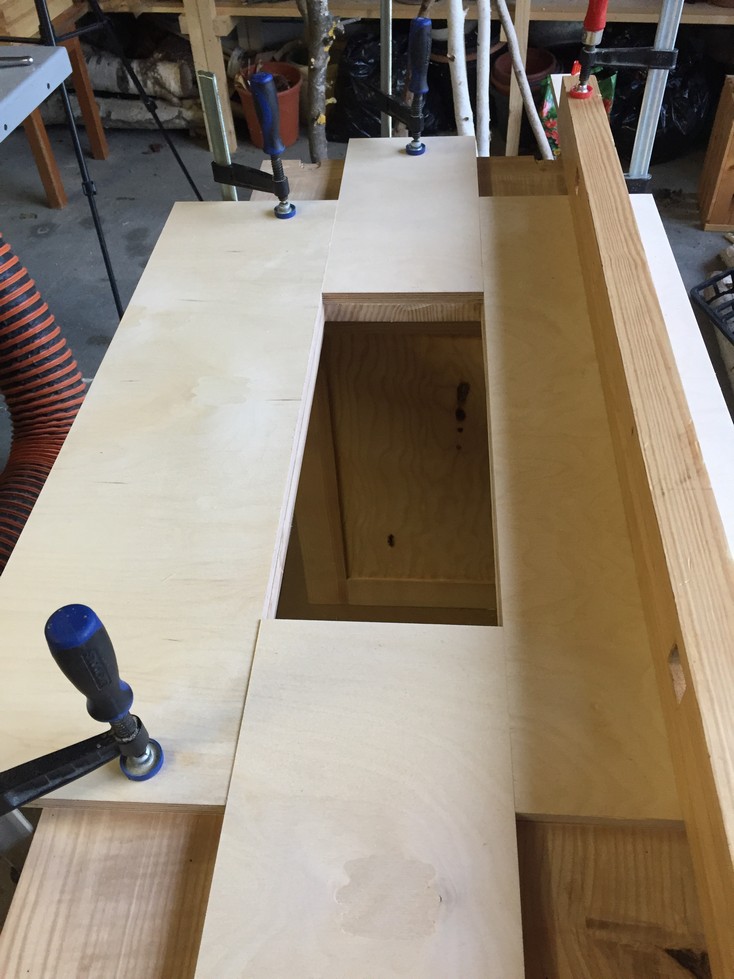

The router creates lots of sawdust so I use the vacuum attachment to get most of it and run the router clockwise around the opening. The result is a nice, cleanly cut opening.


The router bit makes a slight round-over at each corner but it looks good.

It actually didn’t go that well and it’s worth telling so you don’t make the same mistake. You may remember that I’ve mentioned I don’t care much for using a router free hand but this would have gone perfectly, except that I didn’t have one of the clamps tightened sufficiently. When I pushed the router against the pattern on one side, it slipped, causing the router to cut outside the line about 7mm. In order to fix this mistake, I had to reset the pattern and route again. The final result is a clean cut, but now the opening is 7mm larger than planned (not a bad thing) and by the time I smooth the edges of the platform piece there is a much larger gap surrounding it than I like (bad thing). In the end, I decided to make another platform from some extra wood that was planed to 23mm thick (yet another good reason to have extra stock dimensioned for just such an occasion).
I cut it to fit and use a block plane to slightly round the edges and corners. The result is a nice, uniform, 2mm gap all around. What I should have done is instead of using the router, I could have used my block plane to smooth out most of the saw marks and my bullnose/chisel plane to get into the corners. Hand tools over power tools whenever possible.


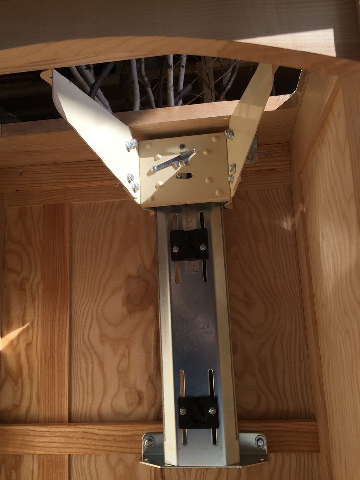
Previously, I had installed two supporting members to the inside of the carcass in order to have a place to mount the lift mechanism. For mounting the lift, I turned the carcass upside down as that made it much easier to position the lift flush with the top and mark for the mounting holes. You’ll notice that the lift has two support wings with 4 bolts each that will hold the platform. You may find that the platform will not be flush all the way around but by loosening these bolts, you can adjust the wings till everything is just right.

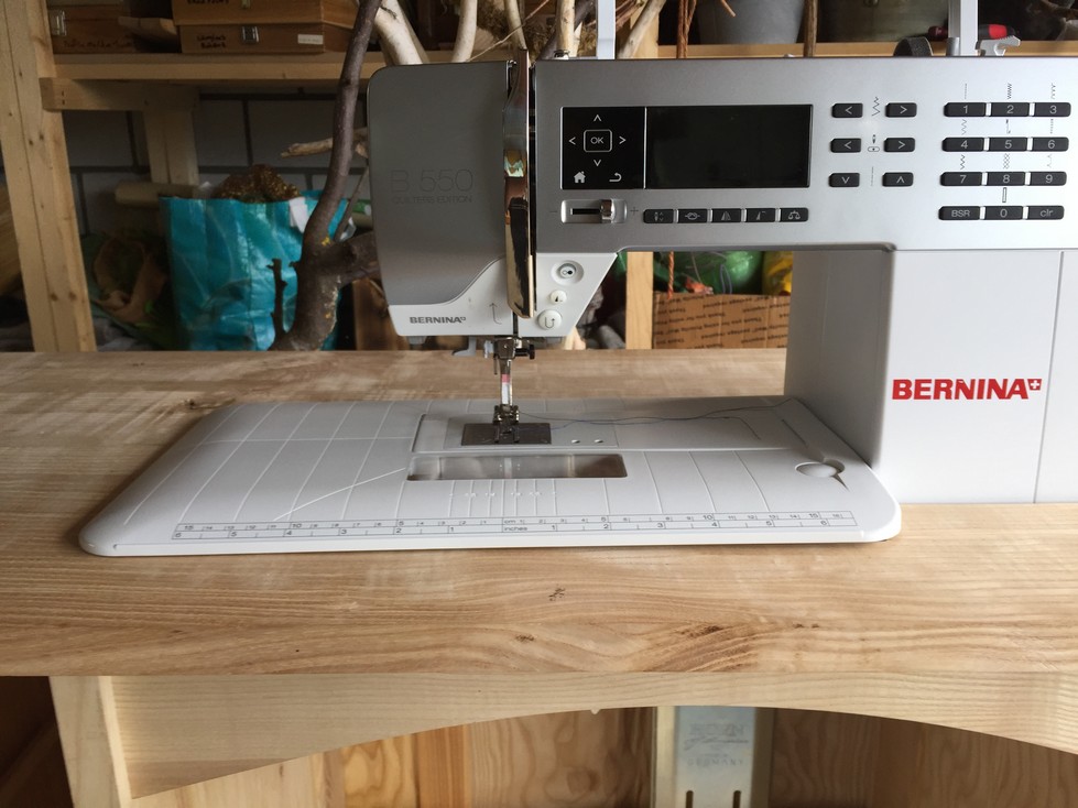
Finally, I get to put the actual sewing machine on the cabinet! I’m seeing a light at the end of the tunnel.

There is proper clearance and the machine can be lowered and raised without anything catching. However, the power receptacle just scrapes by when the machine is lowered and I don’t like that. I clamp the receptacle in a 90 degree bend and pull out a tool I don’t often use while woodworking, my torch. I run the flame lightly all around the receptacle until the plastic is pliable (Please read the Safety Disclaimer 🙂 ). If I leave it clamped until it cools off, it holds its new shape.
In the second position, the machine is lowered about 50mm so the auxiliary platform can be closer to the top panel. I now install the platform and double-check for the notch I have to cut out.

This is what I’m talking about:

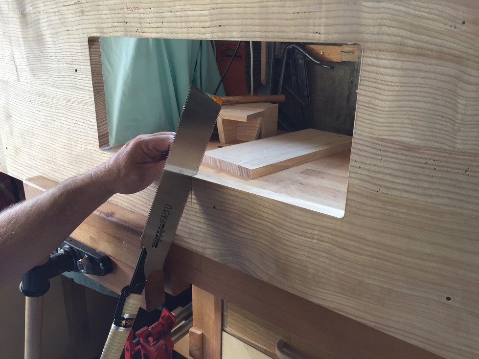
It’s a good thing I double-checked the notch spacing because I had to adjust it about 5mm. This is a simple cut to make so I opt for my handsaw which is a Japanese Ryoba. It has crosscut teeth along one edge and ripping teeth along the other. Japanese saws cut on the pull stroke which is opposite to western saws which cut on the push stroke. The advantage is that the steel can be made much thinner and it is easier to cut a straight line once you get used to it. This is my opinion and the time I spent on Okinawa probably influences me. There are probably more woodworkers that use western style saws than eastern and their opinions may (almost certainly) differ. For me, the experience cutting with Japanese saws is like night and day. I also have a Dozuki for cutting joinery and a Kugihiki for flush cutting.
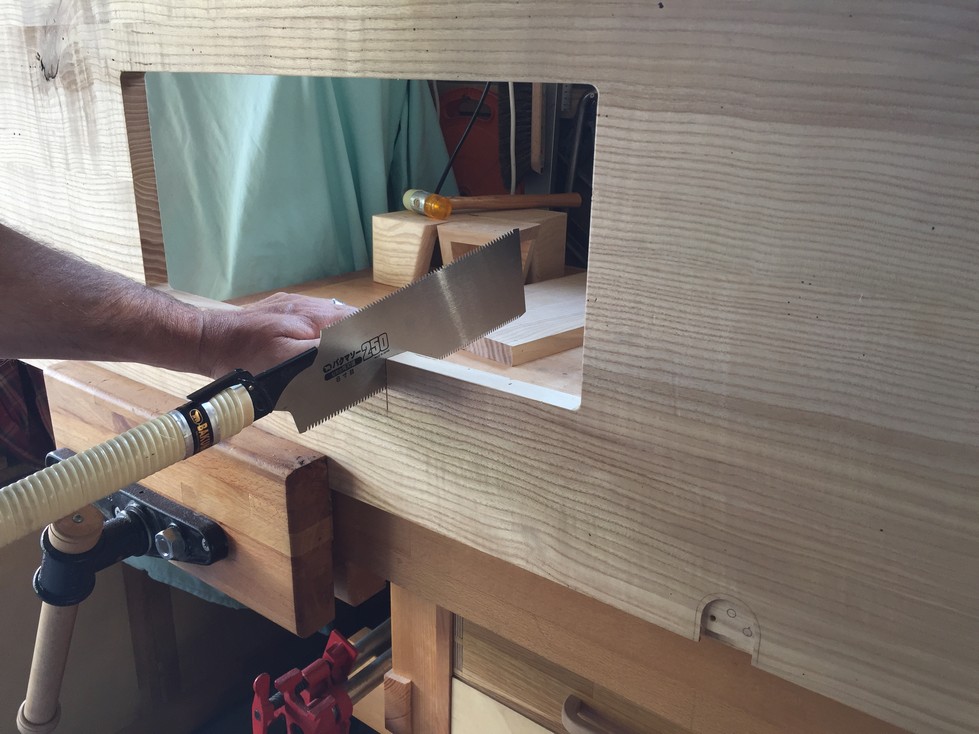
I start by carefully defining the saw kerf square to the panel and then little by little “nibble down” till a kerf defines the line all the way down to the stop.
Normally, I can then finish the cut from top to bottom but when critical, I flip the piece around and cut a defining kerf on the other side. With both kerfs guiding the saw, I can now saw straight down with confidence as the kerfs will ensure the cut stays straight.
With the lift in the second position and the notch cut out, the platform can slide onto the machine with only a small gap on the right side. The left side is pretty flush.
Last but not least, I cut a small square block to fill in the notch when the platform is not being used. The apron assembly underneath supports it so it can remain loose.

Up Next: Final tweaks before smoothing and sanding.
P.S. There may be a delay in the next post as next week I’m being forced kicking and screaming to go to a certain Middle Eastern country for business. Luckily, I’ve not said anything negative about the government…….
Ronny
Nice work!
Brian Witzig
It’s awesome to see this really start to come together! Looks so good.
Have fun in Saudi Arabia! 🙂