
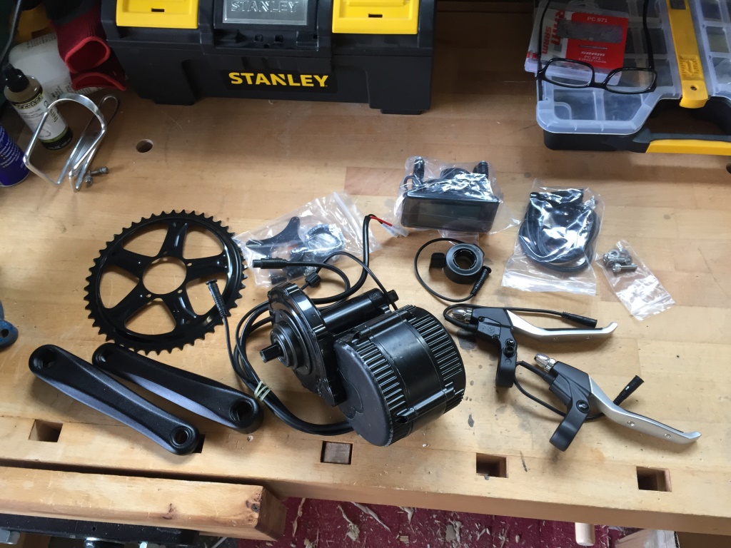
Woohoo! Time to start installing this bright, shiny (OK, black), new kit!
Installation of the Mechanical Components
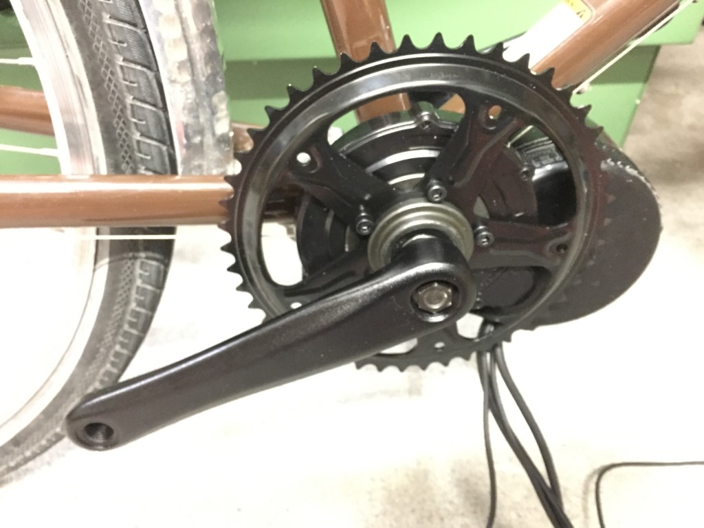
As you can see from this picture below, the motor and drive assembly are meant to be mounted in the bottom bracket (BB) shell of the frame (the same place the previous BB lived).
Unfortunately, it wouldn’t slide in nice so instead of submitting to my base instinct to just wale on it with a big hammer, I took a closer look. Apparently, it is a not-so-uncommon problem that the screw holding the cable guide underneath the BB shell protrudes up into the shell like this:
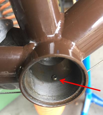
This is not an issue with the normal BB because there is plenty of clearance however, with the BBS02, the outer diameter of the drive shaft matches the inner diameter of the BB shell. The answer was to back out the screw, install the drive unit, and after securing it with the provided bracket and nuts, turn the screw in just enough to seat against the drive shaft housing and prevent it from working loose during a ride. Even if it did work loose, the design of the cable guide is such that the cable will hold it in place.
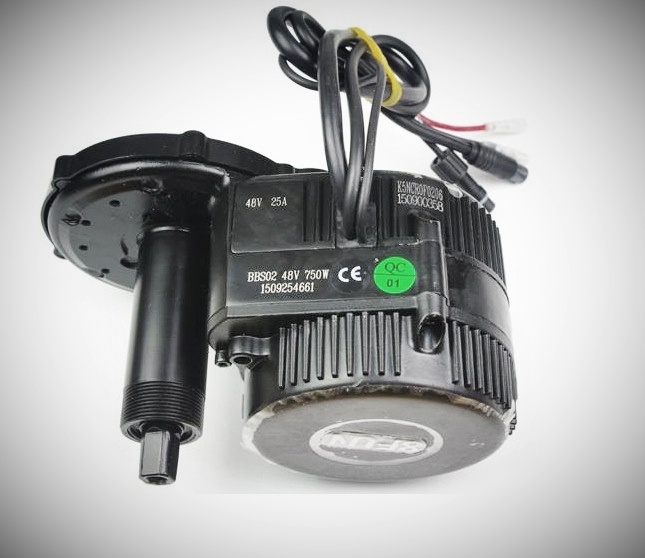
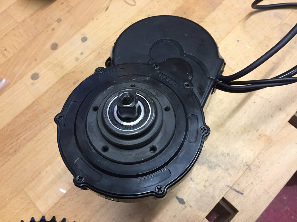
Here is the drive unit in place ready to be secured:
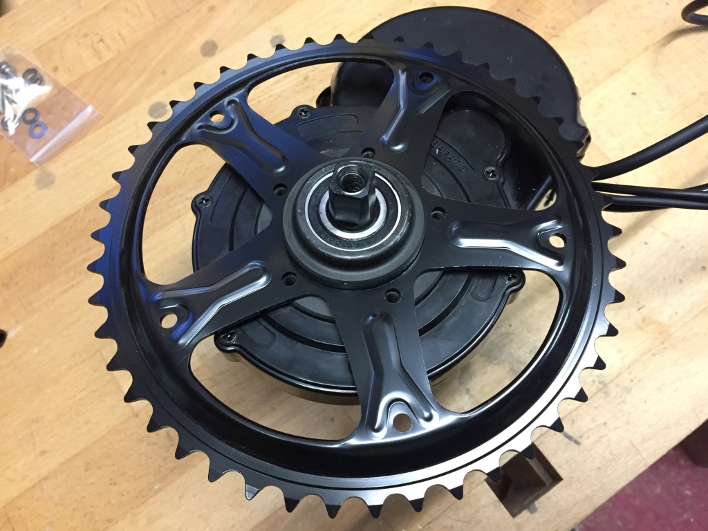
I figure that it will be easier to install the chainring on the bench so I remove the unit again. You will notice the five threaded holes used to bolt the chainring into place.
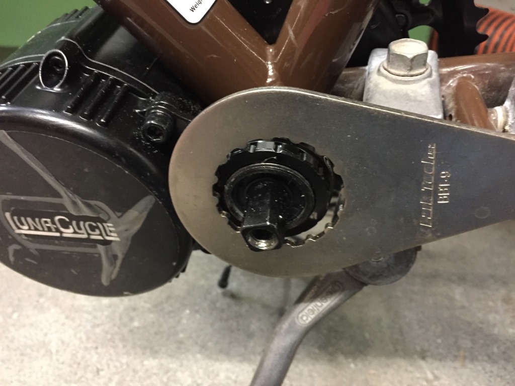
With that accomplished, the drive unit goes back into the BB shell and is secured with a toothed bracket, two cap-head bolts, and BB lock-rings.


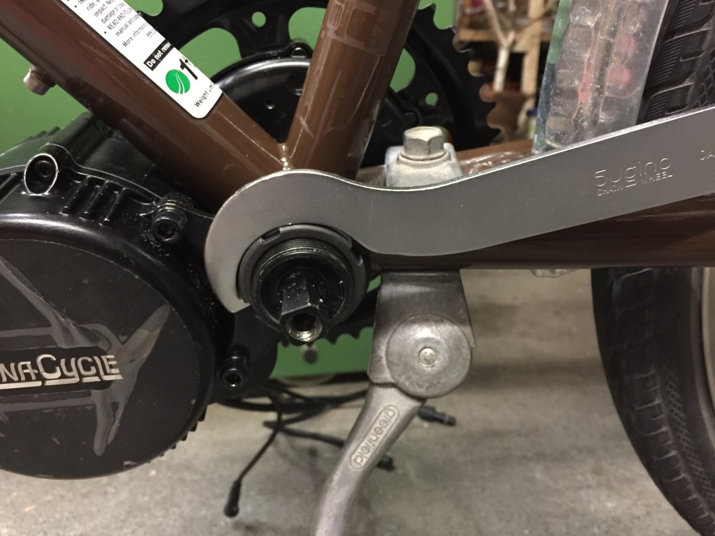
The first lock-ring is a heavy-duty, very solid ring that is best tightened with a BB lock-ring spanner (yes, another special tool).

This tool is one that used to be fairly universal as for many years, lots of BBs consisted of a screw-in cup with two flat edges on the drive side and a lock-ring similar to the one in our kit on the non-drive side. I’ve had this tool since the early 80’s.

The second lock-ring has the purpose of preventing the first one from loosening and again, a special tool. This one has become fairly common as it is used to install the “external bearing” BB.

Of course, in a pinch, you could replace both of these tools with a set of channel-lock pliers, but be careful you don’t strip the lock-ring. Also, wrapping a rag around the ring first will help prevent the pliers from marring the finish.
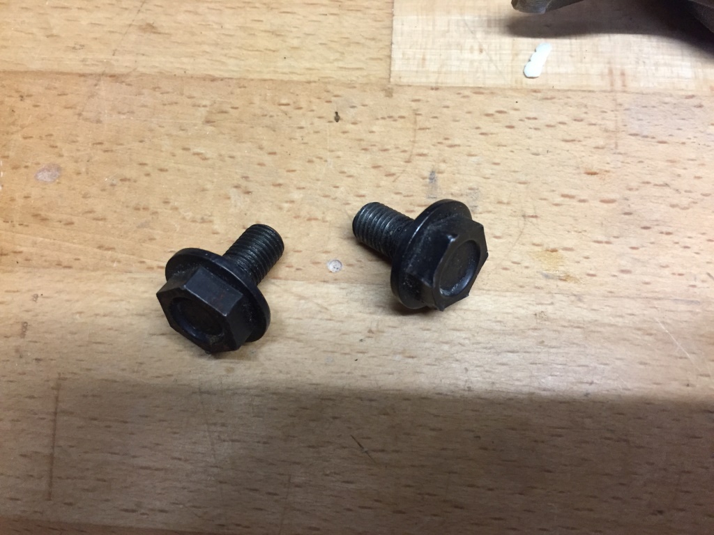
Next step is to install the crank arms. The arms come with the kit however, Bafang either forgot to include crank bolts or the bolts are not standard with the kit. Luckily, I have a few pairs in my box o’ parts. The BB spindle ends and cranks arms are “JIS square taper” which even today is a fairly common standard so a simple 13mm socket wrench is enough to install, no special tools….
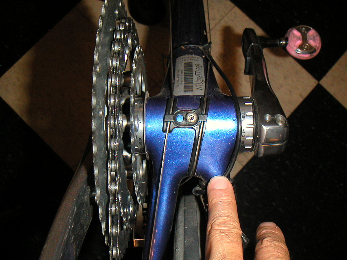
After installing the chain and checking that all gears shift smoothly, there is a bad apple. On the lowest gear (1st gear, which is the largest cog on the cassette) there is a slight noise caused by the chain rubbing the teeth of the cog. In that gear, the chainline is quite extreme. In a perfect world, when the chain is on the middle cog in the rear and on a single chainring in front, the chain should have a nice straight line.
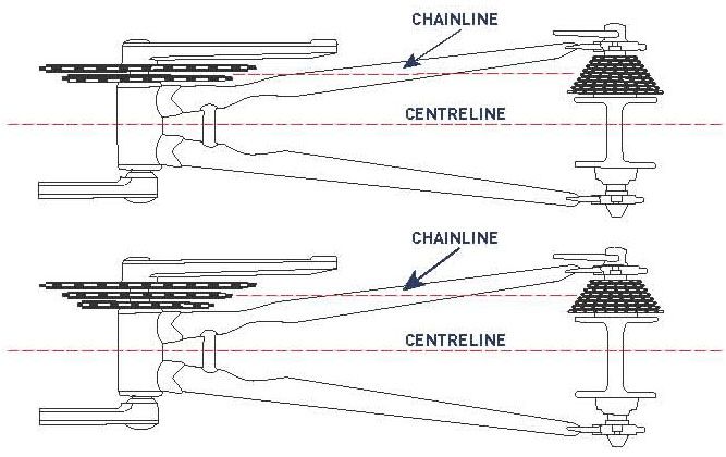
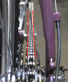
As illustrated in the picture below, the drive unit with stock chainring causes a misalignment that only worsens as I shift down to 1st gear. The noise is only an irritant, I am more worried about the possibility of the chain jumping off the chainring under the considerable torque produced by the motor.

Since this is a common issue, a number of companies have produced chainrings specifically for the BBS02 that attempt to move the chainline closer to the frame. One such chainring is the Lekkie Bling Ring that moves the chainline 9mm towards the centerline which should be more than enough to cure the issue. You can see the offset between the mounting area in the center and the teeth in the picture below to get an idea of the effect.

I have ordered this chainring but have to wait till my son comes back from the US in order to pick it up. Till then, I have adjusted the rear derailleur low-limit screw to prevent Monika from accidentally shifting into 1st gear.

That concludes the mechanical portion of the install!
Installation of the Electrical Components
The power leads from both the battery mounting bracket and the drive unit come as straight wire, taped to prevent accidental shorting during shipment and installation. No connectors.

Based on feedback from multiple sources, a popular connector is the XT-90S which has an anti-spark resistor built into the body of the connector. Nifty. $14.50 for five pairs on Amazon and $9.85 for one pair in Switzerland. Sigh. I needed them now so forked over the cash…..
I don’t want to go into a whole essay on proper soldering, let’s just assume I know what I’m doing (probably to the dismay of my “high reliability soldering” instructor in the Air Force). I stripped about 8mm of insulation from each wire, tinned them, soldered them to the terminals on the connector, applied shrink tubing, and installed the backshell. Piece o’ cake, or as they say in Switzerland “Buebi-einfach” (“so simple a child could do it”, well, maybe not a child…..). When the two halves of the connector are mated, I’ll wrap electrical tape around the entire assembly to protect it from the rain.

The battery mounting bracket is designed to allow positioning it in the same place as the bottle holder. I can re-position the bottle holder to mounting points underneath the down tube of the frame.

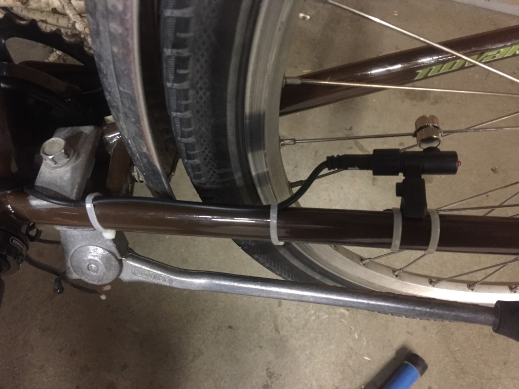
Next I install the speed sensor and magnet to the rear wheel and chainstay. Every time the wheel turns, the magnet is sensed and, with the diameter of the rear wheel entered into the programming, the speed can be calculated. Zip-ties are a great way to neatly route the wiring assembly although I ran out of black zips and will probably replace these white ones soon. I just think it will look better.

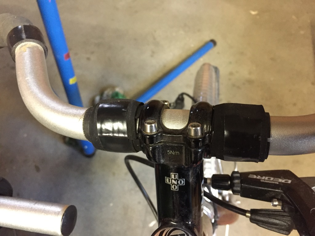
Next is the display that mounts on the center of the handlebars. The mounting bracket supplied is less than ideal because it has to accommodate the largest diameter handlebars on the market and doesn’t come with any spacers. I had to wrap some thick handlebar tape on either side of the stem in order to mount the display securely.

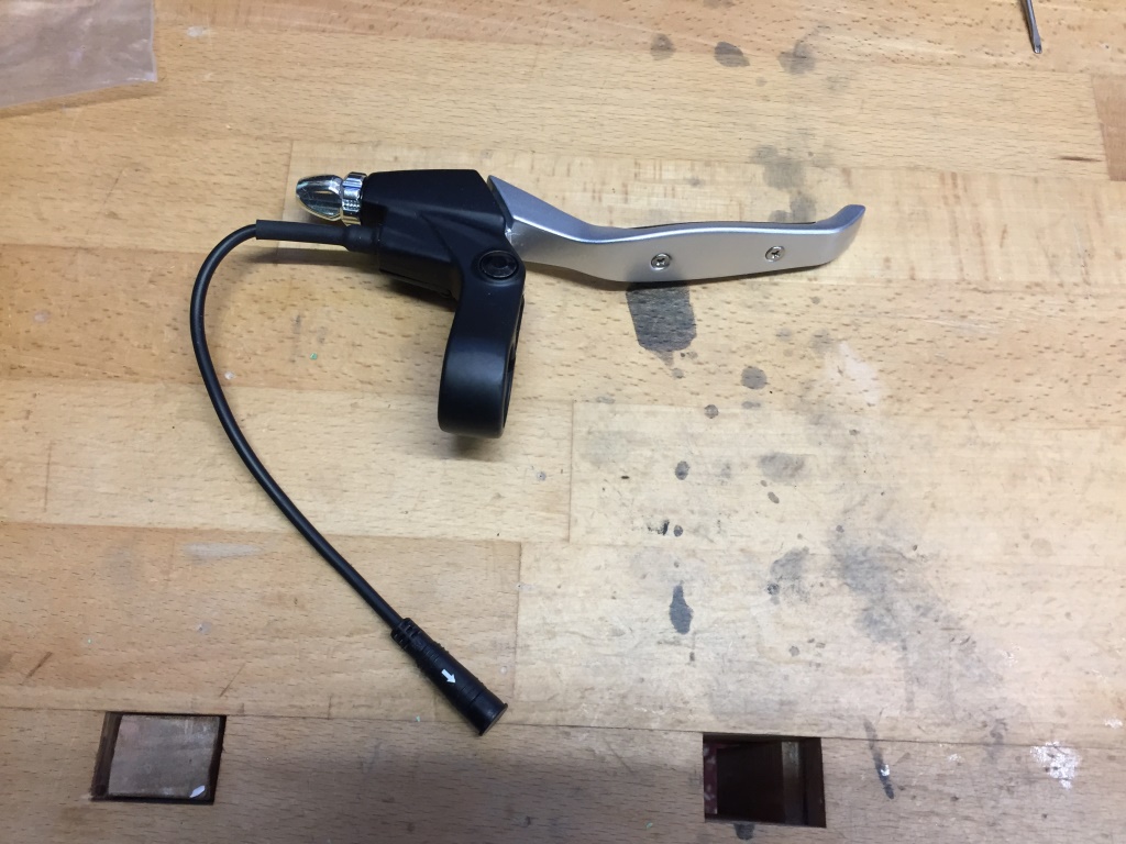
After some thinking about hand position and ease of access while pedaling, I mounted the On/Off PAS control on the left handlebar at the inner edge (these are “trekking” bars that swoop around and provide multiple hand positions for longer rides).
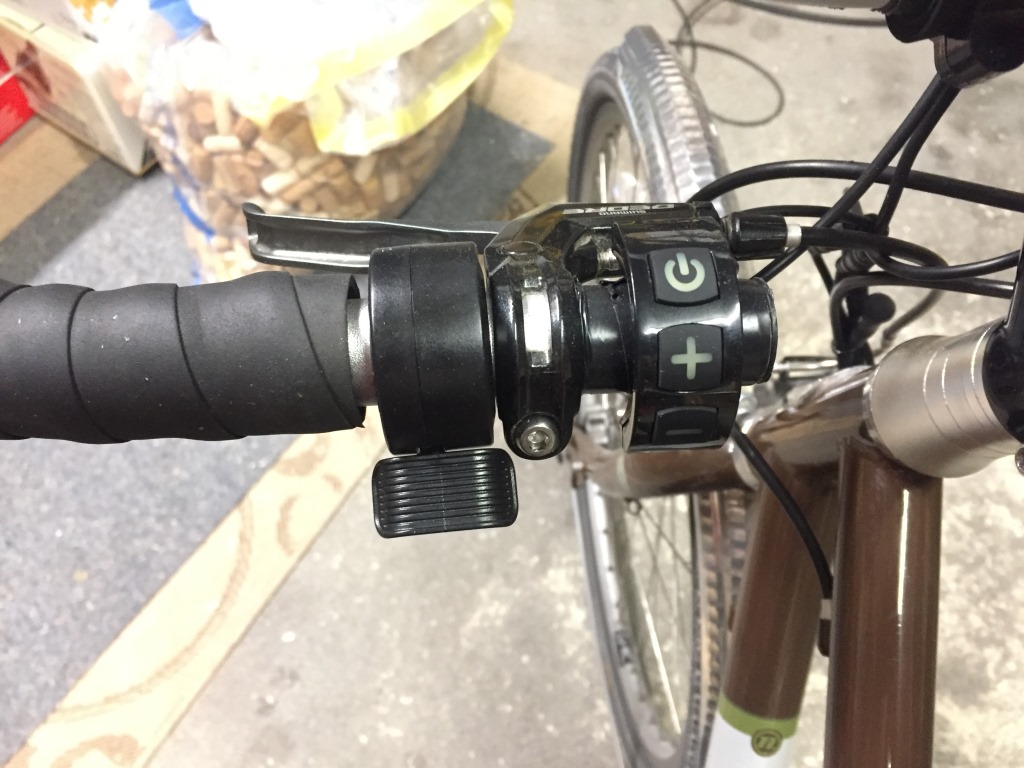
Theoretically, you should turn the system on and set the PAS (pedal-assist level) before you start riding and then leave it alone. Realistically, you will want to be able to adjust the PAS up or down depending on the terrain or how much you feel like pedaling. This is easy to see in practice as Monika wants to be able to pedal normally during most cases but when climbing hills, wishes to have more pedal assist. With the control mounted at the end of the bar, it is easily accessible without getting in the way of normal hand positions. My advice would be, until she’s comfortable with the controls, it’s best to stop before making any changes to the setting.
There are 10 levels of PAS to choose from, 0-9. When set to “0” there is no assist at all, and on “9”, the system helps so much that your feet are just turning and you’re not really putting in any effort except on a really steep hill (like ours). No matter what PAS setting you’re on, the throttle overrides the system so in isolated cases you don’t worry about setting the PAS you can just use your thumb to give yourself some power when you need it and then go back to normal pedaling. Since the throttle needs to be easily accessible without removing your hand from the handlebar, I mount it just to the left of the brake lever clamp.

The system also comes with left and right “e-brake” levers. The purpose of these is to cut off the motor input whenever the brake is applied. Unfortunately, they are large and not very ergonomic.
Monika says she primarily uses the right brake lever (the rear brake, although you get more stopping power with the front) and when there is an urgent stop situation, she applies both brakes at the same time. Based on this input, I decided to only mount the right e-brake lever. I’ll ask again after a few months and may go ahead and mount the left one also. I’m not too worried about emergency situations as this is a redundant safety feature. If you stop pedaling, the motor cuts out automatically so the e-brake is an additional layer of safety. Even if she was using the throttle at the time, the instinct is to grab the brake lever in a stopping emergency thereby releasing the throttle, same idea as in a car.
Now that the display, control, throttle, and e-brake are installed, the only thing left is to connect the wiring harness and zip-tie it neatly to the frame. The designers did a good thing when they made each of the connectors different and color coded so there is no chance of connecting it wrong. It is important to route and secure the wiring such that there is no interference when the handlebars move the wheel to the left and right extremes. In Swiss, my good wife would call this a “cable-salad” but it’s about the best that can be done considering all the wires and cables that have to be routed.

Now I’m ready to install the battery into its mounting bracket. It is important to follow all the special instructions that come with the battery. A really good idea is to do some additional reading about general e-bike battery up-keep. These lithium-ion batteries respond differently than the older ni-cads to charging and usage. For example, while it is fine to fully charge your battery at the end of each day, it has been shown you can increase your total battery life considerably by charging only to 80-90% and not discharge lower than 15%. About once a month of regular use, you should charge to 100% and let the battery sit overnight before using it again. Here is a good link, and another here, that provide more information and forums discussing the ins and outs of battery care and feeding.
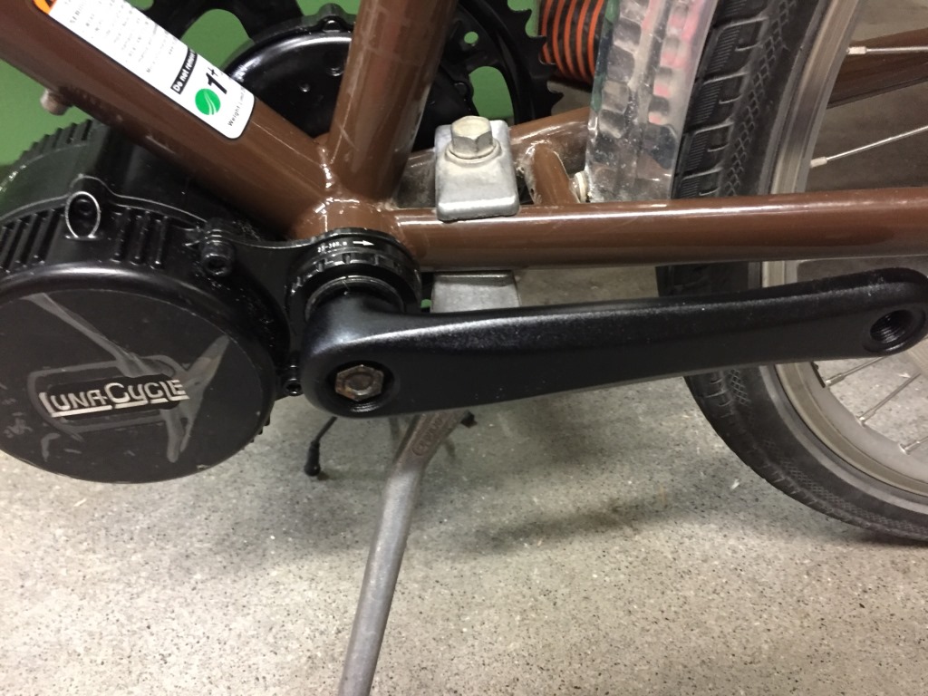
This is what our finished project looks like!
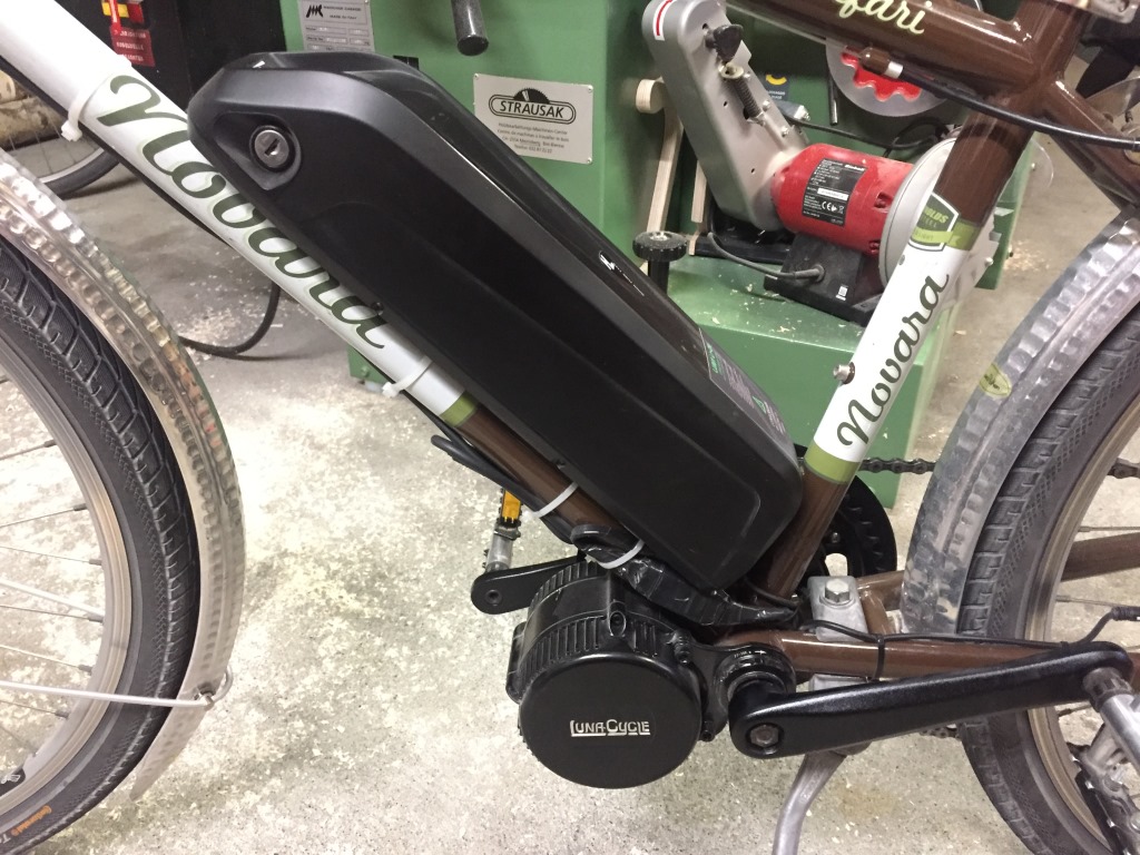
It’s ready to test. In the conclusion of this series I’ll provide my thoughts and Monika’s on how well (or not) this system works. Again, time for a tasty beverage!
Leave a Reply